
Jul 22, 2026Compressed Air Problems
How to Improve Compressed Air Efficiency at the Machine
Learn how to improve machine-side compressed air efficiency by checking pressure, leakage, peak flow, standby consumption, tubing, fittings and air quality.
Compressed air efficiency is often evaluated in the compressor room. Compressor performance, storage capacity, dryer operation and distribution pressure are all important—but compressed air is ultimately consumed at the machine.
Cylinders, pneumatic grippers, vacuum generators, valve terminals, clamping systems and air-blow points can all create unnecessary consumption or unstable operation if the equipment-side air system is not designed correctly.
Improving efficiency therefore requires examining both ends of the system:
- How compressed air is generated and distributed
- How compressed air is regulated and consumed at each machine
Before increasing compressor pressure or replacing equipment, manufacturers should check the actual operating conditions at the point of use.
Why Machine-Side Compressed Air Efficiency Matters
The pressure measured in the compressor room may not be the pressure available at the actuator.
Compressed air travels through main pipes, branch lines, flexible tubing, filters, regulators, fittings and other treatment devices before reaching the machine. Every restriction can contribute to pressure loss.
At the same time, different pneumatic functions may have very different requirements.
For example, a machine may use compressed air for:
- Workpiece clamping
- Robotic gripping
- Machine doors
- Tool-changing mechanisms
- Valve control
- Vacuum generation
- Part ejection
- Air-blow cleaning
- Lubrication-related functions
Supplying all these functions at the same pressure may be convenient, but it is not always efficient.
Does Every Pneumatic Function Need the Same Pressure?
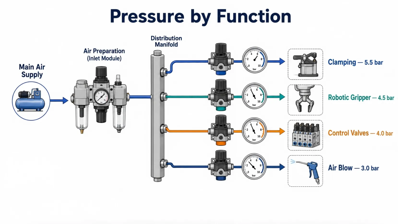
A common machine design uses one regulator for the entire pneumatic system. The pressure is often determined by the function requiring the highest force.
However, a clamping cylinder, robotic gripper, valve terminal and air nozzle do not necessarily require the same pressure.
If one actuator requires higher pressure, increasing the pressure for the whole machine may cause the other circuits to consume more air than necessary.
A better approach is to evaluate pressure by function.
Machine designers and maintenance teams can ask:
- What pressure does each actuator actually require?
- Which function requires the highest force?
- Can air-blow applications operate at a lower pressure?
- Does the pressure remain stable during simultaneous movements?
- Is high pressure compensating for poor piping or excessive pressure drop?
- Can local regulators be used for separate pneumatic zones?
The objective is not simply to reduce pressure. It is to use the lowest pressure that still maintains safe, stable and reliable operation.
Pressure values must always be verified according to the actuator load, required force, cycle time, flow demand and machine safety requirements.
Higher Pressure May Hide a Machine-Side Problem
When a pneumatic cylinder moves slowly or a gripper becomes unstable, increasing the regulator setting may appear to solve the problem.
However, insufficient pressure at the actuator may be caused by other factors, including:
- Undersized pneumatic tubing
- Restrictive fittings
- Excessive hose length
- A clogged filter element
- An incorrectly sized regulator
- Excessive pressure drop across treatment equipment
- High peak-flow demand
- Air leakage
- Supply pressure fluctuations
Increasing the compressor pressure may temporarily compensate for these problems without correcting the underlying cause.
Pressure should therefore be measured while the equipment is operating—not only when the machine is idle.
Measurements should be taken during:
- Simultaneous cylinder movement
- Clamping and unclamping
- Vacuum generation
- Tool changes
- High-flow air-blow operations
- Maximum production speed
This provides a more accurate picture of the pressure actually available to the machine.
Check Peak Flow, Not Only Average Consumption
Average air consumption does not always reveal a machine’s real demand.
Some pneumatic applications consume a large volume of air during a very short period. Examples include:
- Large cylinders moving rapidly
- Multiple actuators operating simultaneously
- Vacuum ejectors
- Air-blow cleaning
- Pneumatic chucks and fixtures
- Rapid tool-changing mechanisms
A system may have sufficient average capacity but still experience pressure drops during peak demand.
When troubleshooting this condition, check:
- Tube inside diameter
- Fitting flow capacity
- Regulator flow capacity
- Local receiver volume
- Valve size
- Simultaneous actuator demand
- Pressure before and after air-treatment components
A larger compressor is not always the first solution. In some cases, correcting a local restriction or providing suitable storage near the machine may be more effective.
How Much Air Does the Machine Consume During Standby?
Many machines continue consuming compressed air even when they are not producing.
Air may still flow through:
- Leaking fittings
- Worn cylinder seals
- Valve manifolds
- Vacuum generators
- Continuous air-blow points
- Pressurized circuits
- Automatic drains that remain open too long
Standby consumption should be measured during production breaks, changeovers and overnight shutdowns.
If the machine requires compressed air only during production, an automatic shut-off or pressure-reduction strategy may help reduce unnecessary consumption. Any isolation system must be designed so that it does not create a safety risk or interfere with required holding functions.
Use Pressure and Flow Data in Context
Digital pressure and flow monitoring can help manufacturers identify abnormal consumption and unstable supply conditions.
Modern sensors can provide:
- Real-time pressure data
- Flow and consumption trends
- Pressure-drop monitoring
- Leakage indications
- Maintenance alerts
- Machine-level energy information
However, a flow meter can show that consumption has increased without independently identifying the cause.
An increase may result from:
- Higher production output
- A changed machine cycle
- A new air-blow process
- A leaking fitting
- A damaged pneumatic tube
- A worn actuator seal
- An incorrect regulator setting
- A blocked air-treatment component
Pressure and flow data should therefore be compared with machine status, cycle count, production output and maintenance records.
Festo notes that pressure monitoring can help detect early signs of leakage, clogged filters and regulator faults, supporting preventive maintenance before these problems result in downtime.
Check Tubing and Fitting Selection
Pneumatic tubing and fittings are sometimes selected primarily according to connection size or installation convenience.
However, their inside diameter and flow characteristics can materially affect machine performance.
Common problems include:
- Tubing that is too small for the required flow
- Long tubing runs between valves and actuators
- Too many elbows or restrictive fittings
- Reducing connectors installed in high-flow circuits
- Tubing that bends or collapses
- Fittings that do not match the tube material
- Leakage caused by poor tube-end preparation
Before increasing the supply pressure, verify that the complete air path can deliver the required flow.
This includes the main branch, air-treatment equipment, regulator, valve, fitting, tubing and actuator connection.
Air Quality and Energy Efficiency Are Different Requirements
Compressed air quality also affects machine reliability.
Liquid condensate, oil contamination and particles may contribute to:
- Valve sticking
- Internal corrosion
- Unstable cylinder movement
- Seal deterioration
- Blocked silencers
- Contaminated vacuum equipment
- Repeated pneumatic component replacement
However, air-quality treatment should not automatically be described as an energy-saving solution.
A point-of-use liquid condensate separator primarily protects downstream equipment by removing liquid water that has already formed in the pipeline.
It does not independently remove water vapor or replace a refrigerated or desiccant dryer when a specified pressure dew point is required.
Any energy-saving claim should be supported by measured pressure drop, leakage, air consumption or maintenance data.
Eight Machine-Side Checks for Better Compressed Air Efficiency
Before increasing the compressor pressure, check the following:
1. Measure the operating pressure
Measure pressure while the machine is running, especially during simultaneous pneumatic movements.
2. Define pressure by function
Determine whether clamping, gripping, valve control and air-blow applications require different pressure levels.
3. Identify peak-flow demand
Check whether short, high-consumption events are causing temporary pressure loss.
4. Review tubing and fittings
Confirm that tube diameter, length and connector capacity match the required flow.
5. Find and repair leakage
Inspect tubing, fittings, valves, cylinders and other pneumatic components.
6. Measure standby consumption
Determine how much air the machine uses when it is not producing.
7. Check treatment-device pressure drop
Measure pressure before and after filters, regulators, separators and dryers under actual flow conditions.
8. Inspect air quality at the machine inlet
Check for liquid water and contamination close to the equipment, rather than relying only on conditions measured in the compressor room.
When Is Point-of-Use Moisture Protection Useful?
Liquid condensate can sometimes form downstream because compressed air continues to cool as it travels through the distribution system.
Point-of-use liquid-water separation may be useful for:
- CNC machines
- Coordinate measuring machines
- Robotic machine-tending cells
- Pneumatic grippers
- Valve terminals
- Automated production equipment
- Machines located far from the compressor room
- Intermittently operated branch lines
A point-of-use separator should be selected according to:
- Working pressure
- Actual and peak flow
- Connection size
- Allowable pressure drop
- Inlet temperature
- Condensate volume
- Drainage requirements
- Available installation space
The device must also be installed in the correct flow direction and positioned so that the collected condensate can be discharged reliably.
Conclusion
Compressed air efficiency does not end at the compressor room.
The condition of the machine-side pneumatic system—including pressure settings, peak flow, leakage, tubing, fittings, standby consumption and air quality—can directly affect energy use and equipment reliability.
Before increasing compressor pressure, identify whether the real problem is:
- Leakage
- Flow restriction
- Excessive pressure drop
- Peak demand
- Incorrect pressure settings
- Standby consumption
- Poor air quality
- Inadequate condensate drainage
The most useful starting point is simple:
Measure pressure and consumption where the compressed air is actually being used.
Frequently Asked Questions
Should every pneumatic function use the same pressure?
Not necessarily. Different functions may require different force, speed and flow. Local pressure regulation can be considered when separate circuits have different requirements.
Is higher compressed-air pressure always better?
No. Excessive pressure may increase consumption, wear and noise. It can also hide restrictions or poor machine-side design.
Why does pressure drop only while the machine is running?
The machine may have high peak-flow demand, undersized tubing, restrictive fittings or insufficient local storage. Static pressure measurements may not reveal these problems.
Can a point-of-use separator replace a refrigerated dryer?
No. A point-of-use centrifugal separator removes liquid condensate that has already formed. It does not independently lower pressure dew point or remove water vapor.
Where should compressed-air quality be checked?
Air quality should be checked near the actual point of use, especially when the machine is far from the compressor room or visible water repeatedly appears at the machine inlet.
Call to Action
Are you experiencing visible water, unstable pneumatic movement or repeated valve and cylinder problems at the machine inlet?
Send us the following application information:
- Equipment type
- Working pressure
- Air flow
- Port size
- Inlet temperature
- Visible condensate condition
- Installation location
We can help evaluate whether point-of-use liquid condensate separation is suitable for your CNC machine or automation equipment.