
Aug 20, 2026Compressed Air Problems
How to Design Compressed Air Piping to Prevent Condensation
See how pipe slope, top-fed branches, drip legs, pipe sizing and temperature changes help prevent condensate from reaching equipment.
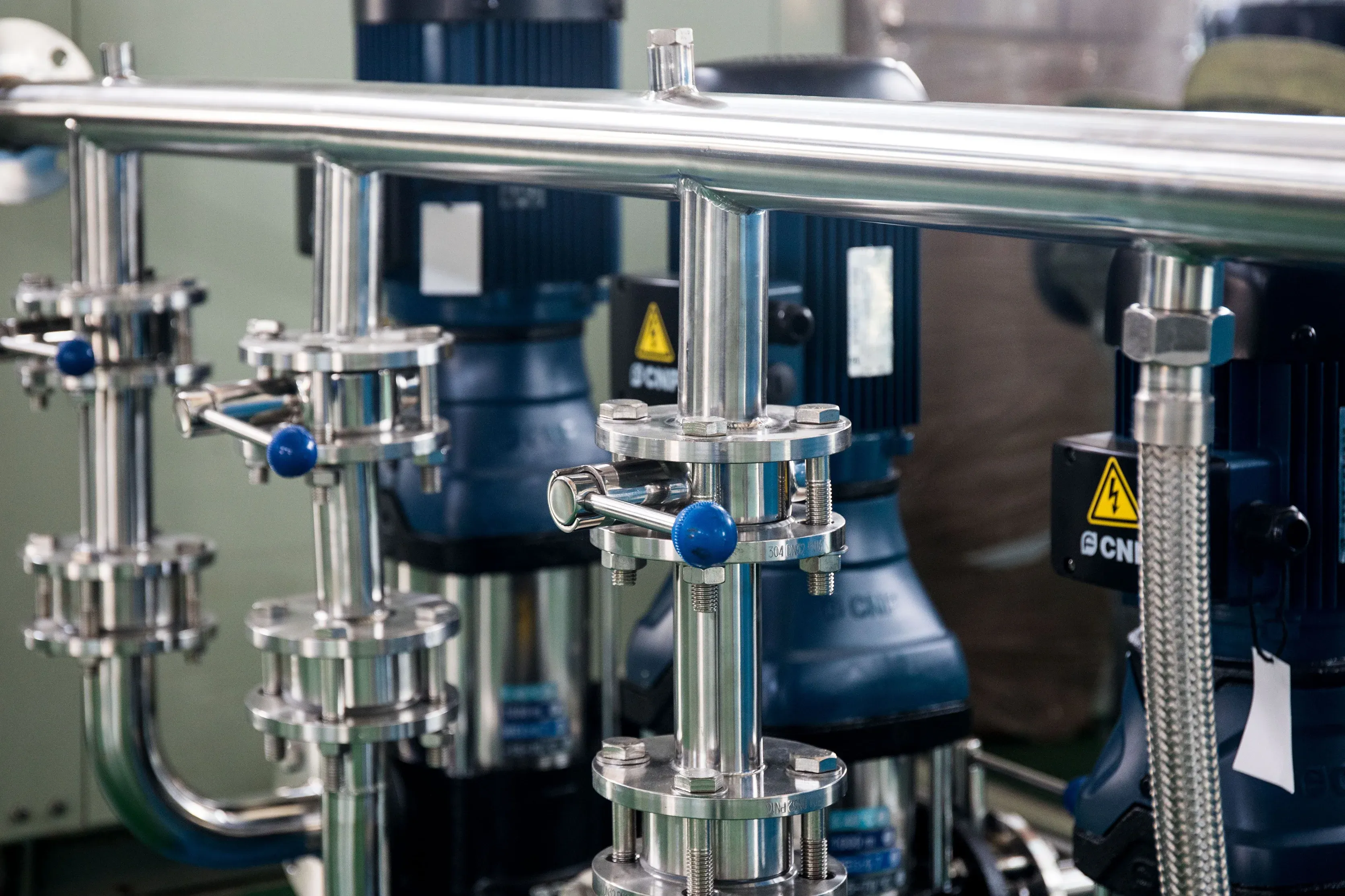
Learn how pipe temperature, slope, branch connections, drip legs and drain placement affect condensate in compressed air distribution systems.
A dryer is the main tool for controlling water vapor, but piping design determines what happens to any liquid that remains or forms during an operating upset.
Poorly arranged compressed air piping can trap condensate, carry it toward equipment and make a minor moisture problem appear much worse.
Good piping does not replace a dryer. It helps the system manage liquid safely and provides early warning when upstream treatment is no longer working.
Identify the Coldest Parts of the System
Condensation occurs when compressed air cools below its pressure dew point.
The coldest part of the system may not be in the compressor room. It may be:
- An outdoor pipe
- An underground section
- An unheated warehouse
- A cold-storage area
- An air-conditioned production room
- A metal pipe near an external wall
For example, air dried in a hot compressor room may still contain enough water vapor to condense when it enters a cooler production area.
Before finalizing the dryer and pipe layout, compare the expected pressure dew point with the lowest pipe temperature.
Slope the Main Header Toward Drain Points
Compressed air headers should not contain uncontrolled low spots.
Where the system design permits, the header should have a deliberate slope toward receivers, drip legs or other controlled condensate collection points. The correct direction and gradient depend on the airflow arrangement and engineering standard used for the installation.
The important principle is that liquid must have a predictable route. A sagging pipe or poorly positioned support can create an accidental water trap.
Take Branch Connections From the Top
Where liquid condensate may be present in a horizontal main header, branch connections are commonly taken from the top of the header.
The branch rises from the main pipe before turning downward toward the point of use. This reduces the likelihood of liquid flowing directly into the branch.
Connecting a tool drop directly to the bottom of a wet header can deliver accumulated condensate straight to the equipment.
Use Drip Legs at Genuine Low Points
A drip leg is a vertical section of pipe designed to collect liquid before it continues downstream.
Drip legs are useful at:
- Header low points
- Long pipe runs
- Changes in elevation
- The bottom of vertical drops
- Areas exposed to significant temperature changes
- Points upstream of sensitive equipment
Each drip leg needs a safe way to discharge condensate, using either a manual or automatic drain.
A drip leg is not a dryer. If it regularly collects large quantities of water, the upstream air-treatment system should be checked.
Understand Why Water Appears at Regulators
Regulators, valves, nozzles and quick couplings create pressure drops. As compressed air expands across a restriction, its temperature can fall.
If the pressure dew point is too high, condensation may become visible at that location.
Moving the filter closer to the coupling may collect some of the liquid, but it does not necessarily correct the underlying dew-point problem.
Avoid Undersized Distribution Pipe
An undersized pipe increases air velocity and pressure loss. High velocity can carry liquid water past drain points instead of allowing it to settle.
Pipe size should be based on:
- Required airflow
- Permitted pressure drop
- Pipe length
- Number of fittings
- Future expansion
- Peak rather than average demand
A properly sized loop system can improve pressure stability and reduce air velocity, but it still requires correctly positioned drains and moisture treatment.
Use Suitable Pipe Materials
All piping, fittings, valves and hoses must be specifically rated for compressed air at the system’s maximum pressure and temperature.
Material selection should also consider:
- Internal corrosion
- Contamination requirements
- Installation environment
- Pressure-drop performance
- Local regulations
- Manufacturer instructions
Unrated plastic water pipe should not be assumed safe for compressed air simply because its printed pressure rating appears sufficient. Compressed gas stores significant energy, and pipe failure can be dangerous.
A Typical Distribution Arrangement
A general system might follow this sequence:
Compressor → aftercooler → separator and drain → wet receiver → prefilters → dryer → dry receiver or main header → distribution loop → point-of-use filtration
Depending on the dryer type and demand profile, the preferred receiver position may differ. The dryer manufacturer’s installation instructions should determine the final arrangement.
Final Design Checklist
Before commissioning the system, confirm that:
- The dryer pressure dew point is below the lowest expected pipe temperature.
- All collection points have accessible drains.
- The header has no unintended low spots.
- Branch drops do not collect liquid directly from the bottom of the main header.
- Drain discharge lines cannot create backpressure.
- Pipe diameter is adequate for peak demand.
- Outdoor sections are designed for local temperatures.
- Sensitive processes have appropriate point-of-use treatment.
- All components are rated for compressed air service.
The purpose of good piping design is not to hide a moisture problem. It is to prevent liquid from reaching equipment, make drainage predictable and reveal treatment failures before they cause production damage.